How to Test a Golf Cart Solenoid: 4-Terminal Test with a Multimeter
A solenoid has two circuits doing two different jobs, and testing it properly means testing both. This is the full multimeter procedure, including how to tell a failed solenoid from something that only looks like one.
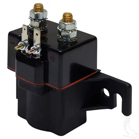
- A four-terminal solenoid has two large power terminals and two small coil terminals. They are separate circuits and each needs its own test.
- A click only proves the coil moved the plunger. It says nothing about whether the contacts inside are actually passing current.
- The definitive test is a voltage drop across the two large terminals while the cart is trying to draw current. That is what finds burnt contacts.
- Most solenoids condemned as faulty are innocent. The fault is usually upstream in what energises the coil.
- Always disconnect the main battery pack before touching the large terminals. This circuit can deliver enough current to weld tools.
The solenoid is one of the most frequently replaced parts on a golf cart and one of the most frequently replaced unnecessarily. It sits between the battery pack and the controller or motor, acting as a heavy duty remote switch: a small current through its coil closes a large contact that carries the main drive current. That two circuit arrangement is the key to testing it, because a solenoid can fail in either half, and the symptoms overlap enough that guessing gets it wrong.
This guide covers the complete test with a basic multimeter. It is worth doing properly before buying a part, because the two most common outcomes of a careful test are that the solenoid is fine and something upstream is at fault, or that the solenoid has failed in a way that is obvious once you measure it rather than listen to it.
Safety first. The two large terminals are connected directly to the battery pack and can deliver hundreds of amps into a dropped spanner. Disconnect the main pack before any work that involves touching those terminals, remove rings and watches, and use insulated tools. Reconnect only for the specific live tests described below, and keep hands and metal clear of both large terminals while the pack is connected.
Understanding the Four Terminals
Nearly every golf cart solenoid has four terminals arranged as two pairs, and knowing which pair does what makes the whole test straightforward.
The two large terminals are the power side. One connects toward the battery pack and the other toward the controller or motor. These carry the full drive current, which is why they use heavy cable and large studs. When the solenoid is at rest these two terminals are not connected to each other. When it activates, an internal contact bridges them.
The two small terminals are the control side, and they connect to the coil, an electromagnet inside the solenoid. When the cart decides you want to move, it sends a small current through this coil, the resulting magnetic field pulls a plunger, and the plunger closes the contact between the large terminals. The click you hear is that plunger moving.
This is why a click is such weak evidence. It confirms the coil works and the plunger moved. It tells you nothing about the condition of the contact surfaces that plunger just closed, and those surfaces are exactly what wears out.
| Terminal pair | Circuit | What it does | How it fails |
|---|---|---|---|
| Two large studs | Power | Carries full drive current when the solenoid closes | Contacts burn, pit or weld from arcing |
| Two small posts | Coil control | Small current energises the electromagnet | Coil goes open circuit or shorts internally |
What You Need
A basic digital multimeter with resistance, DC voltage and continuity functions is sufficient. You do not need a clamp meter or a load tester for this procedure. You will also want insulated spanners for the terminal nuts, and wheel chocks, because part of this test involves the cart being live and capable of moving.
Before starting, note the cart’s pack voltage and whether the solenoid coil is rated for full pack voltage or for a lower voltage. Coil supply arrangements vary between manufacturers and models, and there is no single correct coil voltage across all carts. Check the label on the solenoid itself, which normally states the coil rating, and match any replacement to it.
Test 1: The Coil Resistance Test
This checks whether the electromagnet is intact. Disconnect the main battery pack first, then remove the two small wires from the coil terminals so you are measuring the coil alone and not the circuit around it.
- Set the multimeter to resistance, on a low range if it is not autoranging.
- Place one probe on each small terminal.
- Read the value and compare it to the coil specification for your solenoid.
What you are looking for is a stable reading that agrees with the exact coil family and voltage rating. Published continuous-duty examples range from single-digit ohms at 12 volts to well over 100 ohms at 48 volts, so a generic low-ohm expectation is unsafe. The exact expected value depends on the coil voltage rating and the specific part, and it is printed in the manufacturer’s specification for that solenoid rather than being a universal figure. Do not compare your reading against a number from a different cart or a different brand, because the correct value legitimately differs between them.
The two readings that are unambiguous regardless of the specification are the extremes. An open circuit, shown as OL or infinity, means the winding is broken and the coil is dead. A reading of zero or very close to it means the winding has shorted. Either condemns the solenoid.
Test 2: Is the Coil Actually Being Told to Close?
This is the test that saves the most unnecessary purchases, and it is the one most often skipped. A solenoid that never clicks is frequently a perfectly good solenoid that is never being asked to close.
Reconnect the coil wires and the battery pack, chock the wheels, and set the multimeter to DC voltage. With the probes on the two small coil terminals, have someone turn the key on, select a direction and press the accelerator, and watch the meter.
If voltage appears at the coil when the pedal is pressed and the solenoid does not click, the solenoid coil is at fault and Test 1 will confirm it. If no voltage appears at the coil, the solenoid is not the problem at all. Something upstream is failing to complete the control circuit, and that list includes the key switch, the direction selector, the pedal switch or sensor, the seat or brake interlock, a fuse in the control circuit, and the controller itself.
That upstream group is where most no-click faults actually live. The microswitches in that chain are a common failure point and are covered in detail in the guide to testing golf cart microswitches, and the tow and run switch will also break this circuit when left in the wrong position, as explained in the guide to the golf cart tow and run switch.
Test 3: The Contact Test, Which Is the One That Matters
This test finds the failure mode that the click test misses entirely: contacts that close mechanically but no longer conduct properly because their surfaces have burnt or pitted from arcing.
There are two ways to check the contacts, and they answer slightly different questions.
The static continuity check. With the pack disconnected and at least one large cable removed so you are not reading through the rest of the cart, set the meter to continuity or resistance and probe across the two large terminals. At rest there should be no continuity. Energise the coil, and continuity should appear. This confirms the contact is closing at all, but it passes even quite badly degraded contacts, because it tests with almost no current flowing.
The voltage drop test, which is definitive. This one is done live, with the cart trying to draw current. Set the meter to DC voltage, place one probe on each large terminal, chock the wheels, and have someone attempt to drive the cart while you watch the reading.
The principle is simple. A healthy closed contact is very nearly a piece of wire, so the voltage difference across it while current flows should be very small, on the order of a fraction of a volt. A burnt contact has resistance, and resistance under current produces a voltage drop. If you see a substantial voltage across the two large terminals while the cart is trying to move, current is being wasted as heat in the contacts and the solenoid has failed, regardless of how healthy the click sounds.
This is also the explanation for the classic complaint of a solenoid that clicks but the cart will not move, which is covered from the symptom side in the guide to a solenoid that clicks but will not move.
Reading Your Results
| Symptom | Coil resistance | Voltage at coil on pedal | Drop across large terminals | Conclusion |
|---|---|---|---|---|
| No click at all | Open circuit | Present | Not applicable | Coil failed, replace solenoid |
| No click at all | Normal | Absent | Not applicable | Solenoid is fine, fault is upstream |
| Clicks, cart does not move | Normal | Present | Substantial | Contacts burnt, replace solenoid |
| Clicks, cart does not move | Normal | Present | Very small | Solenoid is fine, fault is downstream |
| Cart will not stop | Any | Any | Very small at rest | Contacts welded closed, replace immediately |
The row worth dwelling on is the last one. A solenoid whose contacts have welded shut leaves the drive circuit permanently connected, which means the cart can move as soon as a direction is selected and may not stop when you expect it to. That is a serious safety fault and the cart should not be used until it is resolved. It is covered separately in the guide to welded solenoid contacts.
When It Is Not the Solenoid
Two patterns account for most solenoids replaced without benefit. The first is the no-voltage-at-coil case from Test 2, where the control circuit never energises the coil and the solenoid was never involved. The second is the healthy-contacts case, where the solenoid closes and conducts properly but the cart still does not move, meaning the fault lies beyond it in the controller, motor or drivetrain.
There is also a third pattern worth naming: a solenoid that fails repeatedly. Replacing it again is not the answer, because a solenoid that burns out its contacts quickly is usually being asked to do something it should not have to. Excessive current draw, a failing controller, or a loose high-current connection that arcs will all destroy a new solenoid in short order. If you are on your second or third solenoid, the cause is elsewhere and the solenoid is the victim. A running-hot solenoid is an early sign of exactly that, and it is covered in the guide to what it means when a solenoid is hot.
Published Coil Resistance by Contactor Family
Coil resistance rises sharply with coil voltage because a higher-voltage coil needs less current to produce the same magnetic pull. That is why a healthy 48-volt continuous-duty contactor can measure well over 100 ohms while a healthy 12-volt version of the same family measures in the single digits. Compare only with the exact family and coil-voltage row on the label.
| Manufacturer family | Duty rating | 12 V coil | 24 V coil | 36 V coil | 48 V coil |
|---|---|---|---|---|---|
| Trombetta PowerSeal continuous duty | 100 percent continuous | 13.5 ohms | 48 ohms | 105 ohms | 192 ohms |
| Trombetta Bear continuous duty | Continuous family | 7.7 ohms | 32 ohms | 69 ohms | 126 ohms |
| Trombetta PowerSeal intermittent duty | 25 percent duty | 5.5 ohms | 21 ohms | 48 ohms | 86 ohms |
Those are Trombetta datasheet values at 25 C for the named families. They are reference points, not universal pass limits for Club Car, E-Z-GO, Yamaha, or an unmarked replacement. Meter tolerance, coil temperature, lead resistance, and suppression components can change the field reading. An open circuit still indicates a broken winding. A stable result that differs from the exact datasheet requires confirming the part number and coil option before condemning it.
Use voltage and resistance together
Ohm’s law connects the values: current equals voltage divided by resistance. A 48 V PowerSeal continuous coil at its 192 ohm nominal value would draw about 0.25 A in the simple steady-state calculation. That relationship is useful for spotting the wrong coil option, but use the manufacturer’s published pull-in and hold data for design decisions. Do not size a control circuit from a resistance reading alone.
Diodes, Resistors, and the Meter Trap
A coil is an inductor, which means it creates a voltage spike when its magnetic field collapses. Manufacturers offer suppression across the small terminals to control that spike. Albright lists diode, diode plus resistor, and bidirectional diode options on its SW80 and SW180 contactors. The option matters during testing and replacement.
- Disconnect both small wires and photograph their polarity before measuring. A diode-protected contactor can be polarity sensitive.
- Measure resistance in both lead directions. A diode path may influence one polarity of the meter and make the reading look lower or unstable.
- Use diode-test mode if the suppression device is accessible and the datasheet identifies its arrangement. Do not assume a molded component is only a resistor.
- Compare the isolated coil with the exact option code. Measuring through the cart harness can include controller inputs, a resistor, or another parallel path.
- Reconnect the small wires exactly as found. Reversing a diode-protected coil can create a short or leave the suppression ineffective.
The resistor sometimes seen across the large terminals is a different component. It is commonly used as a precharge path so the controller input capacitors charge before the main contacts close. It does not belong in the coil-resistance measurement. Remove at least one end from the circuit if a large-terminal continuity check is being confused by that parallel path. The exact Trombetta 684-3681-012-14 reference shows why SKU-level identification matters.
Continuous Duty Is Part of the Electrical Specification
A traction contactor can remain energized through a long drive, so its coil must tolerate that duty. Trombetta’s published PowerSeal continuous family is rated for 100 percent duty. The visually similar intermittent family is rated for 25 percent duty. Its lower coil resistance means more heat when energized for the same voltage. Installing it where the cart expects continuous operation can produce a hot coil, dropout, welded contacts, or another early failure even when the terminal pattern fits.
Brand names do not establish coil voltage. Club Car, E-Z-GO, and Yamaha have each used different electrical architectures across model and production families, and public owner manuals do not provide a reliable universal contactor table. Confirm pack voltage, coil label, suppression polarity, mounting, contact configuration, and the serial-matched parts listing. No broad brand part-number table is published here because that would encourage unsafe substitution.
How to Judge Contact Voltage Drop
Albright publishes typical new-contact drop of 40 mV at 100 A for the SW80 family and 30 mV at 150 A for the SW180 family. Those are manufacturer benchmarks for new contactors under stated current, not universal service rejection limits. A golf cart test without current measurement cannot be compared directly to either number.
- Measure directly from one large stud to the other while the correct drive load is applied. Probe the studs, then the cable lugs, to separate internal contact loss from a loose connection.
- Repeat under the same operating condition. A reading that jumps, rises quickly, or changes when the case is tapped supports damaged contacts.
- If a DC clamp meter is available, record current with voltage drop and compare the pair with the exact contactor datasheet. Higher current naturally creates more drop.
- Compare pack voltage at the contactor input with voltage delivered at the output. If most of the missing voltage is across the closed contactor, the fault is local.
- Stop if a stud, cable, or case heats rapidly. Heat is evidence of power loss and can damage the replacement if the terminal joint is the real cause.
Test both circuits, and do not accept a click as proof of anything. Measure the coil with the pack disconnected, then check whether voltage even reaches the coil when the pedal is pressed, because a solenoid that is never told to close is a solenoid that is not at fault. Finish with the voltage drop across the two large terminals while the cart is trying to draw current, since that is the only test that reliably exposes burnt contacts. Compare the coil resistance against the specification printed for your solenoid rather than a figure borrowed from another cart, and if you are replacing your second or third solenoid, stop and look for what is destroying them.
Frequently Asked Questions
Can I test a golf cart solenoid without removing it?
Yes, and it is better to. The coil voltage test and the voltage drop test both need the cart connected and trying to draw current, so they can only be done in place. Only the coil resistance test benefits from disconnecting the small wires, and even then the solenoid can stay mounted.
What should a golf cart solenoid coil read in ohms?
It depends on the coil voltage rating and the specific part, so check the specification for your solenoid rather than using a universal number. What is unambiguous is the extremes: an open circuit means a broken winding and a reading near zero means a shorted one, and either condemns the solenoid.
My solenoid clicks but the cart won’t move. Is the solenoid bad?
Not necessarily. The click only proves the plunger moved, not that the contacts are conducting. Measure the voltage across the two large terminals while someone tries to drive the cart: a substantial reading means the contacts are burnt, while a very small reading means the solenoid is doing its job and the fault is further downstream.
Is it safe to test a solenoid myself?
It is, provided you respect the large terminals, which connect directly to the battery pack and can deliver enough current to weld a dropped tool. Disconnect the pack before touching them, remove rings and watches, use insulated tools, and chock the wheels before any live test, since some tests involve the cart attempting to move.
Why does my new solenoid keep failing?
A solenoid that fails repeatedly is usually a symptom rather than the cause. Excessive current draw, a failing controller, or a loose high-current connection that arcs will all destroy a replacement quickly. Look for a cause outside the solenoid rather than fitting another one.