
The “Click of Death” Fix
You hear the click but the cart will not move. That click only proves the coil pulled in, not that the main contacts carried motor current. Here is how to test the low-current coil and the high-current contacts separately, with real coil-resistance bands, contact-drop numbers, and OEM references.
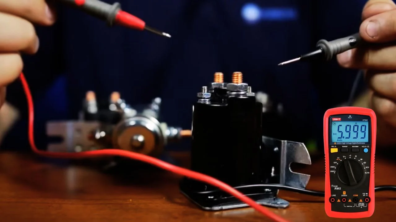
- The click is the coil, not the contacts. Diagnose the low-current coil circuit and the high-current contact circuit as two separate problems.
- Contact health is a loaded voltage-drop test. Albright rates about 40mV across new SW80 contacts at 100A and new SU280 contacts at 250A; a repeatable drop over 0.20V is a practical service trigger.
- Coil resistance has no single value. Screening bands calculated from Albright’s 7 to 13W continuous coil data give roughly 177 to 329 ohms at 48V; infinite reading means an open coil.
- The precharge resistor is not the coil. Curtis uses a 250 ohm MP-2 and Alltrax uses 470 or 1000 ohm; controller B+ sitting 1 to 5V below pack with the key off is normal through that resistor.
The click of death fools more owners than almost any other golf-cart fault. You press the pedal, the solenoid clicks, and the cart sits dead. That click proves that something moved, it does not prove that the main contacts carried motor current. The fix is to stop treating the solenoid as one part and start testing its two separate circuits: the low-current coil that pulls the plunger in, and the high-current contacts that are supposed to pass power to the motor. First confirm the contactor nameplate, coil voltage, controller family, and wiring diagram, because coil resistance varies with coil design, duty, suppression device, and temperature.
Two Circuits, Two Tests
The coil is a small electromagnet energized by the pedal or key sequence; if it gets its rated command voltage and clicks, that half is working. The contacts are heavy copper faces that carry hundreds of amps to the motor, and they burn, pit, and carbonize over time. A solenoid can click perfectly while its contacts are too damaged to pass current, which is precisely the click of death. Test each independently, and never chase the contacts before confirming the coil is even being commanded.
The Diagnostic Table
| Test | Good evidence | Failed or suspect evidence | Important condition |
|---|---|---|---|
| Coil resistance, power isolated and coil wires removed | A stable finite value matching the coil datasheet or calculated power band | OL or infinite means an open coil; near 0 ohms means a short or wrong measurement path | Measure directly across the isolated coil; a diode or economizer makes polarity and meter mode matter. |
| Coil command voltage | The coil receives its rated command while the pedal or key requests closure | Missing or low command points upstream to key, pedal, direction, controller, lockout, or wiring | Measure at both small terminals while commanded, not one terminal to an assumed ground. |
| Main-contact drop while energized under measured load | Albright publishes about 40mV for new SW80 contacts at 100A and about 40mV for new SU280 contacts at 250A | A repeatable drop above 0.20V is a practical inspect and service trigger, not a universal warranty limit | Current must be flowing; with no load a damaged contact can still read nearly 0V. |
| Main-contact state while not commanded | Pack voltage appears across the open main terminals, subject to the precharge path | Near 0V can indicate welded contacts; full controller B+ with key off can also indicate welding | Curtis notes controller B+ may sit 1 to 5V below pack through the precharge resistor with key off. |
| Mechanical sound | One clean closure and release | Buzzing, chatter, delayed release, or repeated clicking points to low coil voltage or mechanical damage | Do not cycle a chattering contactor under motor current. |
Calculated Coil-Resistance Screening Bands
Albright publishes 7 to 13W for continuous coils and 15 to 20W for intermittent coils in the SW80 family. Using R = V squared / P gives the calculated cold-screening bands below. These are screening bands, not measured specs for every coil code, so confirm the actual coil duty and suppression option before condemning a part.
| Nominal coil | From 7 to 13W continuous-coil data | From 15 to 20W intermittent-coil data |
|---|---|---|
| 12V | 11.1 to 20.6 ohms | 7.2 to 9.6 ohms |
| 36V | 99.7 to 185.1 ohms | 64.8 to 86.4 ohms |
| 48V | 177.2 to 329.1 ohms | 115.2 to 153.6 ohms |
A reading outside this calculated range does not automatically fail a different manufacturer or a contactor with an economizer. Infinite resistance is still strong evidence of an open winding, and a reading near meter-lead resistance is strong evidence of a short only after all parallel wiring is removed.
OEM and Controller References
Confirm every part number by serial, model, voltage, controller, and terminal layout before ordering.
| Vehicle or controller | Reference (confirm by serial) | Application note |
|---|---|---|
| Club Car DS legacy applications | Club Car 101908701 | OEM service reference. Confirm voltage, controller, mounting, and terminals. |
| E-Z-GO RXV with Danaher controller | E-Z-GO 609428 | Factory parts material lists a heavy-duty 36V solenoid in the RXV Danaher configuration. Do not substitute for a Curtis-equipped RXV from the number alone. |
| Yamaha G29 / YDRE catalog examples | JU6-H1950-00, later JW9-H1950-20 relay assemblies | Genuine catalog references vary by production year. |
| Curtis 1207B installation | Albright SW80 or SW180 family | Curtis recommends these families and identifies a Curtis MP-2 250 ohm, 5W precharge resistor. |
| Alltrax controller installation | 470 ohm or 1000 ohm precharge resistor | Use the value the controller diagram specifies, not whichever resistor is on hand. |
The Precharge Resistor Is Not the Coil
The precharge resistor sits across the main contactor to charge the controller input capacitors gradually and reduce inrush at closure. Curtis 1209 and 1221 guidance says controller B+ can sit 1 to 5V below pack with the key off through the precharge path, which is normal. If B+ reads full pack voltage when the contactor should be open, remove and test the 250 ohm resistor as the manual directs before concluding the main contacts are welded. Mixing up the precharge resistor and the coil resistance sends many techs chasing the wrong part.
A clicking solenoid that will not move the cart is usually burnt main contacts, but prove it the right way: confirm the coil is commanded and healthy, then measure the main-contact drop under real load. A repeatable drop over about 0.20V condemns the contacts, while near-zero drop with no load proves nothing. Replace the solenoid with the correct OEM or controller-matched part, and check the precharge resistor before blaming welded contacts. When you wire the new unit, install the coil suppression diode with its striped end to the positive activation terminal, or you will create a short.
Frequently Asked Questions
Why does my golf cart solenoid click but the cart won’t move?
The click means the magnetic coil is pulling in, but the internal high-current contacts are likely burnt, pitted, or carbonized, so power never reaches the motor. Confirm it with a voltage-drop test across the two large posts under load: a healthy solenoid drops only tens of millivolts, while a repeatable drop over about 0.20V means the contacts are bad and the solenoid must be replaced.
How do I test a golf cart solenoid?
Test the two circuits separately. For the coil, isolate it and measure resistance for a stable finite value (infinite means an open coil). For the contacts, press the pedal so the solenoid clicks and measure voltage across the two large posts while current flows: both posts should read near full pack voltage, and a large drop from the input post to the output post means the contacts are failing.
Which way does the diode go on a golf cart solenoid?
The small suppression diode across the activation terminals is directional. The end with the silver or grey stripe connects to the positive activation terminal, the wire coming from the pedal switch. Installing it backward creates a short circuit, so match the stripe to the positive small terminal every time.
What is the difference between the coil resistance and the precharge resistor?
They are different parts. The coil is the electromagnet inside the solenoid, with a resistance in the hundreds of ohms on a 48V cart. The precharge resistor sits across the main contactor to gently charge the controller capacitors and cut inrush, typically 250 ohms on Curtis or 470 to 1000 ohms on Alltrax. A controller B+ that reads a few volts below pack with the key off is that precharge resistor working normally, not a welded contact.
