Club Car 48V Battery Wiring Diagram: DS and Precedent Layouts
Trace the series path on six 8-volt or four 12-volt Club Car packs, identify the true pack terminals, and check voltage without guessing at model-specific charger wiring.
- Voltage adds in series. Six 8-volt batteries or four 12-volt batteries can both form a nominal 48-volt pack.
- Use the outer pack ends. The vehicle positive and negative cables belong on the two free ends of the complete series chain.
- Do not copy accessory wires blindly. Charger receptacle, OBC, controller, and sense-lead routing changes by year and electrical system.
- Verify before moving a cable. Identify the serial number, photograph every connection, disable the cart, and follow the matching service manual.
A Club Car 48V battery wiring diagram is useful only when it matches the battery count and the car. The large interconnect cables form one simple series chain, but smaller charger and control wires are not universal across DS and Precedent generations. This guide separates those two jobs so a correct pack layout does not become an incorrect vehicle connection.
Identify the car and battery layout
Start with the model and serial number, not a photo from another cart. Club Car produced the DS across many electrical generations, while the Precedent arrived later and used several drive and charging systems. The Club Car serial number lookup helps narrow the year and platform before any cable is removed.
Then count batteries and read the voltage molded or printed on each case. A six-battery pack built from 8-volt batteries is nominally 48 volts. A four-battery pack built from 12-volt batteries is also nominally 48 volts. Battery shape alone is not a reliable voltage label. Record the existing cable routing with clear photos and mark each battery position before disassembly.
Put the cart in the manufacturer-specified tow or maintenance state, switch the key off, remove the key, set the direction selector to neutral, chock the wheels, and disconnect charging power. Battery packs can deliver destructive fault current. Use insulated tools and the serial-specific manual.
How the 48-volt series path works
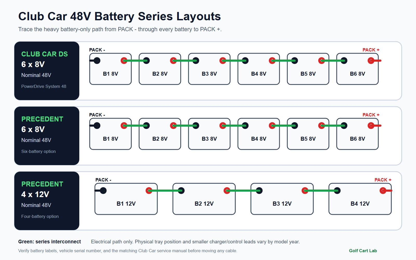
Series wiring connects the positive terminal of one battery to the negative terminal of the next. Each interconnect advances the electrical path through another battery. The two terminals left unused by the interconnect chain become the pack terminals. One is pack negative and the other is pack positive.
The arithmetic is straightforward: six batteries at 8 volts each equal a nominal 48 volts, and four batteries at 12 volts each equal the same nominal pack voltage. The physical tray positions may zigzag, so follow terminal polarity rather than assuming the nearest posts connect together. A series chain should have no positive-to-positive or negative-to-negative interconnect in its main path.
This page focuses on flooded lead-acid layouts documented for DS and Precedent cars. It is not a lithium conversion diagram. A lithium pack may use a battery management system, contactor, precharge circuit, charger interlock, and low-current harness that cannot be inferred from lead-acid cable placement. See the 48V lithium conversion guide before changing battery chemistry.
DS and Precedent layout map
| Configuration | Main series sequence | Manual-backed scope |
|---|---|---|
| Club Car DS, six 8V | Pack negative, battery 1 through battery 6 in series, pack positive | PowerDrive System 48 DS owner documentation |
| Club Car Precedent, six 8V | Pack negative, battery 1 through battery 6 in series, pack positive | 2009 to 2011 Electric Precedent service manual |
| Club Car Precedent, four 12V | Pack negative, battery 1 through battery 4 in series, pack positive | 2009 to 2011 Electric Precedent service manual |
The combined hero diagram redraws these arrangements as an electrical series path and a tray-oriented reference. It deliberately labels polarity and battery count more prominently than cable color. Replacement cables are not always the factory color, and a faded boot is not proof of polarity.
On the cited Precedent service manual, the four-battery voltage test places the red meter probe on battery 1 positive and the black probe on battery 4 negative. The six-battery test uses battery 1 positive and battery 6 negative. DS tray positions differ from the Precedent illustration, which is why a Precedent picture should not be used as a DS placement map.
Find pack positive and pack negative
- Trace the complete chain. Starting at one free terminal, follow each heavy interconnect through every battery. A valid path visits each battery exactly once.
- Identify the two free ends. The free negative end is pack negative. The free positive end is pack positive. These are not necessarily on the batteries closest to the controller.
- Separate large and small conductors. Tag the vehicle mains, charger receptacle conductors, and every smaller control or sense lead separately.
- Compare with the correct schematic. Match model, model year, controller family, and charging system before reconnecting any non-main lead.
If the existing wiring is already disturbed, do not use cable length as the deciding evidence. Aftermarket cables may have been replaced with different lengths. Build and verify the battery-only series chain first, then use the correct schematic to land the vehicle and charging conductors.
Safe voltage checks after wiring
Before reconnecting the vehicle, set a properly rated digital multimeter to DC volts and confirm the meter leads are in the correct jacks. Measure each battery directly across its own posts, then measure across the identified pack ends. Pack voltage should be close to the sum of the individual battery readings. A negative sign means the probes are reversed; it does not mean the pack itself has negative voltage.
Resting voltage and loaded voltage answer different questions. Trojan recommends disconnecting loads and charging sources and allowing roughly one hour of rest before using open-circuit voltage as a state-of-charge check. The Club Car Precedent manual gives 46 to 49 volts as a good fully charged result during its specified discharge-machine load test. Do not apply that loaded-test band to an at-rest pack.
Record individual readings. One weak unit can let the total look plausible at rest and collapse under load. For cable and connection trouble, use the method in the battery cable voltage-drop guide. A voltage-drop test under controlled load finds resistance that an ohmmeter may miss.
Charger, OBC, and sense-wire differences
The heavy battery chain is common electrical theory. The smaller charging connections are system-specific. Many DS PowerDrive arrangements use an onboard computer, commonly called the OBC, and the charger receptacle includes a sense function. Later Club Car configurations can route charge control differently. Moving every small wire to the terminal that looks similar can bypass monitoring, prevent charger enable, or leave a control circuit without its reference.
Use the wiring diagram for the exact car when a receptacle fuse link, sense lead, OBC cable pass-through, controller feed, or accessory reducer is involved. If the complaint is a charger that will not start, preserve the pack layout and diagnose the charging path separately with the Club Car OBC and smart-charger guide. Bypassing parts is not a substitute for proving the fault.
Common wiring mistakes
- Using a generic 48V drawing as a physical tray map for both DS and Precedent.
- Connecting a main interconnect between like polarities and breaking the series chain.
- Choosing pack ends by location instead of tracing the complete chain.
- Stacking dirty or loose lugs, which creates heat and voltage loss.
- Reusing a damaged cable because it still passes a no-load continuity test.
- Copying charger or OBC leads from a different year or controller system.
Clean and inspect the posts and lugs before final torque. Replace swollen, cracked, heat-darkened, or badly corroded components. Follow the battery and vehicle specifications for hardware and torque because overtightening can damage a lead terminal. The battery maintenance guide covers routine cleaning and electrolyte care after the wiring is confirmed.
A correct Club Car 48V pack has one uninterrupted series chain and two verified outer pack ends. Treat that battery chain as one task and the model-specific charger, OBC, controller, and sense wiring as a second task. If the serial-specific schematic is unavailable, stop before reconnecting the small conductors.
Frequently Asked Questions
Does a Club Car 48V pack use four batteries or six?
It can use either four 12-volt batteries or six 8-volt batteries, depending on the model and configuration. Read every battery label and use the matching Club Car diagram.
How are Club Car 48V batteries connected?
The main batteries are connected in series: positive on one battery to negative on the next. The two free outer terminals become pack positive and pack negative.
Are Club Car DS and Precedent battery layouts the same?
No. Both can use a 48-volt series pack, but tray placement and the vehicle, charger, OBC, or sense connections can differ. Use the model-year-specific manual.
Where should a meter be placed to check the full pack?
Place the probes across the verified pack positive and pack negative terminals. Trace the complete series chain first rather than choosing terminals by their physical location.
Can the same diagram be used for a lithium conversion?
No. A lithium conversion may add a battery management system, contactor, charger interlock, and low-current harness. Use the battery maker and vehicle conversion instructions.
Updated September 2026: Rechecked against Club Car DS PowerDrive System 48 documentation, the 2009 to 2011 Electric Precedent service manual, and Trojan battery testing guidance.