Battery Cable Voltage Drop Test
New batteries but the cart still dies on hills? Corrosion inside a cable acts like a kink in a hose. Here is how to measure the hidden resistance under load, normalize it to real current, and know exactly when to clean versus replace.
- Static voltage lies. A corroded cable reads a healthy 12V parked, then eats several volts once you pull 200 to 300 amps up a hill. Voltage drop only appears under load.
- A drop is meaningless without the current behind it. The same joint drops 0.05V at 50A and 0.20V at 200A, so measure amps with a DC clamp and convert to milliohms with R = V / I.
- Screening bands at 100A: under 0.10V pass, 0.30 to 0.40V clean and retest, over 0.50V repair or replace. These are workshop bands, not a warranty spec, and must be normalized to your test current.
- Gauge does not rescue a bad crimp. A 3 milliohm joint burns 120W at 200A, enough to soften a lead post. Always torque to the battery-terminal spec with a calibrated inch-pound wrench.
You just spent several hundred dollars on batteries, but the cart still dies on hills. The cables look fine from the outside, yet inside them corrosion is quietly eating the connection. The only way to catch it is a voltage drop test, and the only way to do that test correctly is under load with the current measured. Get those two things right and you stop replacing good parts.
The Ghost in the Machine
Static voltage, measured while parked, only shows potential energy. Voltage drop measures the energy lost trying to push current through a bad wire while it is working. The relationship is simple: voltage drop = current times resistance. If a corroded cable has high resistance and you pull 300 amps up a hill, that single cable can eat 4 volts. Your motor gets 44V instead of 48V, and the missing energy turns into heat at the joint.
Load Test Procedure
You cannot run this test parked, because voltage drop only happens when current flows. Charge the pack first, secure the cart, and use insulated probes.
- Set the multimeter to 20V DC. Test one cable at a time.
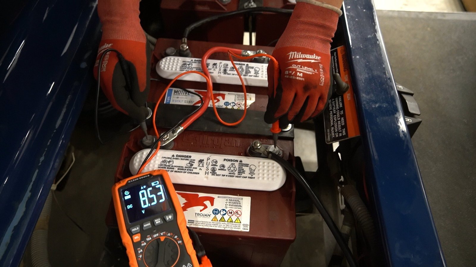
- Put the red probe on the battery post and the black probe on the other end of that same cable, at the next post.
- At rest the reading should be about 0.00V, because no current means no drop.
- Apply a repeatable load: drive the same hill at the same speed, or brake-stall against a chock, and capture both the peak voltage drop and the current at that instant with a DC clamp.
The Verdict: Current-Normalized Screening Bands
A voltage drop result is only meaningful with current flowing. The same 1 milliohm connection drops 0.05V at 50A, 0.10V at 100A, and 0.20V at 200A. Record pack current at the moment you record the drop, then calculate resistance as R = V / I. The bands below are read at 100A. At 200A the same 1, 3, and 5 milliohm resistances produce 0.20, 0.60, and 1.00V, so always compare like with like.
| Drop at 100A | Calculated resistance | Interpretation | Action |
|---|---|---|---|
| Under 0.10V | Under 1.0 milliohm | Low drop for a high-current joint | Record and compare with equivalent joints. |
| 0.10 to 0.29V | 1.0 to 2.9 milliohms | Investigate, especially if a matching cable is much lower | Inspect crimp, stud, strands, heat damage, and terminal seating. |
| 0.30 to 0.40V | 3.0 to 4.0 milliohms | Excessive service-screening band | Disconnect safely, clean or recrimp, torque correctly, retest at the same current. |
| Over 0.50V | Over 5.0 milliohms | Severe loss at this test current | Repair or replace the failed cable or connection before further high-load use. |
These are transparent screening bands, not a universal Club Car, E-Z-GO, or Yamaha warranty specification. Normalize them to the measured current every time.
Cable Gauge Figures Need a Temperature Context
Bigger cable helps, but a gauge number without a temperature rating is meaningless. The continuous copper lead-wire ampacities below come straight from the Southwire lead-wire reference.
| Copper conductor | 60C | 75C | 90C | 105C |
|---|---|---|---|---|
| 6 AWG | 53A | 67A | 77A | 86A |
| 4 AWG | 71A | 89A | 104A | 116A |
| 2 AWG | 96A | 121A | 141A | 158A |
Those are temperature-rated continuous figures, not permission to size a motor cable from one column alone. Vehicle cables see short high-current bursts, lug and enclosure heat, vibration, and repeated acceleration. Alltrax separately describes stock 6 AWG vehicle cable as suitable for about 300A in its controller application note and recommends 4 AWG with a 400A controller or a non-stock motor. That is controller-application guidance, not a substitute for the cable maker’s thermal table. Gauge also does not rescue a poor termination: power lost at a joint is P = I squared times R, so a 3 milliohm joint dissipates 120W at 200A. That concentrated heat softens lead posts, relaxes nuts, and oxidizes strands under the insulation.
Model-Specific Terminal Torque References
A loose joint creates heat and excess torque distorts the lead post, so identify the exact terminal type and use a calibrated inch-pound wrench. Confirm every figure against the manual for your cart.
| Platform or terminal | Published torque | Scope (confirm by model) |
|---|---|---|
| Club Car 2019 Precedent battery cable nut | 110 in-lb (12.4 Nm) | Factory service-manual figure for that model. |
| E-Z-GO RXV battery terminal hardware | 98 to 105 in-lb (11 to 12 Nm) | Factory service-manual range for the referenced RXV configuration. |
| Yamaha Drive2 with Trojan T-875 terminal | 95 to 105 in-lb (11 to 12 Nm) | Yamaha battery manual figure for the named battery and terminal. |
| Trojan flooded ELPT/EHPT/EUT/LT/WNT/DWNT/UT terminals | 95 to 105 in-lb | Terminal-type specification, not universal for every Trojan terminal. |
| Trojan M6 terminal | 30 in-lb | Shows why one remembered torque value can damage different hardware. |
Trojan also publishes 50 to 70 in-lb for EAPT/AP, 100 to 120 in-lb for IND, 85 to 95 in-lb for M8, and 120 to 180 in-lb for ST. Use the value for the actual battery and vehicle, not a number remembered from a different cart.
Where the Hidden Resistance Actually Hides
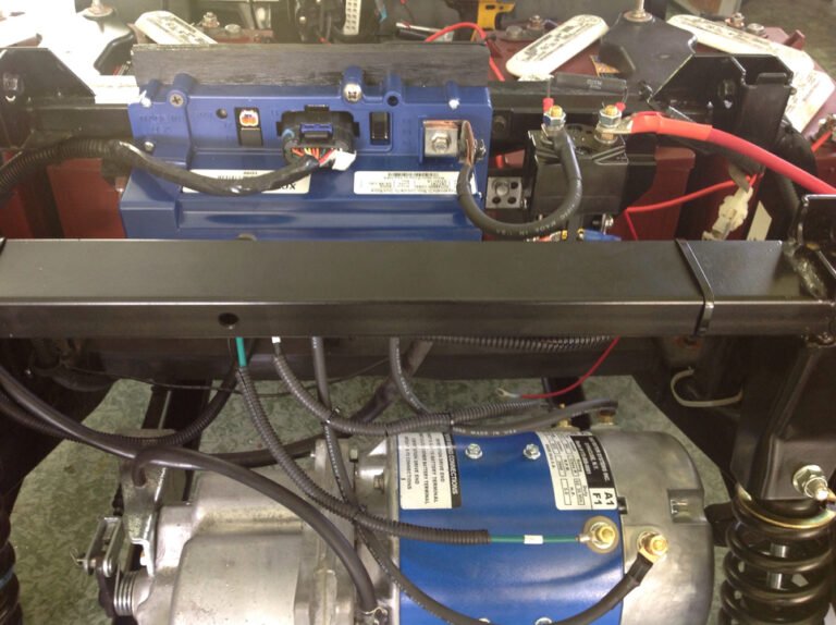
Cable-to-cable drop is only half the story. The most overlooked resistance lives in the connections that never see a wire brush: the solenoid main lugs, the controller B+ and B- posts, and the two heavy cables at the motor. On a Club Car Precedent from 2004 up, the factory ran a single 6 AWG loop through six batteries, and the lug that bolts to the solenoid is a classic hot spot because it sits under the seat where road spray reaches it. On the E-Z-GO TXT from 1994 to 2013, the weak link is usually the negative cable at the controller, which loosens with vibration and reads a clean static voltage right up until you climb a hill. Test each junction the same way: one probe on the incoming stud, one on the outgoing terminal, under load. More than 0.1V across a single bolted joint is your problem, not the battery behind it.
Lithium Carts Are Not Immune
A lithium conversion does not end cable worries. LiFePO4 packs hold full voltage until nearly empty, so a marginal cable that used to hide behind sagging lead-acid voltage now shows up as a sudden BMS trip when the controller demands 300-plus amps and the cable cannot pass it. On Yamaha Drive2 and E-Z-GO RXV conversions the original factory cabling is often too light for the higher sustained current, and the fix is the same 4 AWG welding-cable upgrade. If a lithium cart cuts out under hard acceleration but tests fine at rest, run the loaded drop check before blaming the battery.
Two Mistakes That Fake a Bad Cable
Before you condemn a cable, rule out two false positives. First, a low or imbalanced battery in the string sags hard under load and makes every downstream cable look guilty, so confirm each battery is charged and balanced first. Second, cheap probes with worn tips add their own resistance and invent a tenth of a volt that is not there, so press firmly on clean bare metal and re-check a known-good joint to confirm your meter reads near zero. Skip these and you will replace a good cable while a tired battery keeps stealing your range.
The useful diagnosis is not that the pack sags. It is the exact number of milliohms and watts lost at one component under a documented current. Finish every job with a full-path test, pack positive to controller B+ and pack negative to controller B-, then divide any excessive result into smaller segments until the loss is isolated. When you replace cable, step 6 AWG up to 4 AWG welding cable and re-torque after the first few drives. Write your good under-load numbers on tape inside the battery compartment so a five-minute re-test six months later catches a degrading joint before it strands you.
Frequently Asked Questions
What is a voltage drop test on a golf cart?
A voltage drop test measures the voltage lost as current travels through a cable or connection. Unlike a continuity test, it must be done under load while the cart accelerates, because the loss only appears when current is flowing. It is the only accurate way to detect internal corrosion inside battery cables and bolted joints.
What is an acceptable voltage drop for battery cables?
Read at about 100 amps, under 0.10V across a cable or joint is good, 0.30 to 0.40V means clean and retest, and over 0.50V means repair or replace. These are workshop screening bands, not a warranty figure, and must be normalized to your actual test current, since the same joint drops twice as much at 200 amps as at 100 amps.
Why are my golf cart battery cables getting hot?
Heat is a byproduct of resistance. A loose or corroded connection blocks smooth current flow, and the energy that cannot pass through turns into heat: a 3 milliohm joint burns about 120 watts at 200 amps. That is enough to soften a lead post and melt a terminal, so a cable or lug that is hot after driving needs to be cleaned or replaced, not just tightened.
What size cable should I use for a golf cart?
Stock 6 AWG handles roughly 300 amps in typical vehicle use, but with a 400 amp controller or a non-stock motor, step up to 4 AWG welding cable. Do not size from a single ampacity column: golf cart cables see short high-current bursts, lug heat, and vibration, so give yourself margin and pair the bigger cable with a properly torqued crimp.