
Club Car Precedent Speed Sensor: Testing Fixes
A sudden 8 MPH cap usually means the Club Car Precedent speed sensor has tripped limp mode, the IQ controller’s failsafe when it loses the motor RPM signal. Here is how to test the three-wire Hall sensor with real service-manual values and restore full speed.
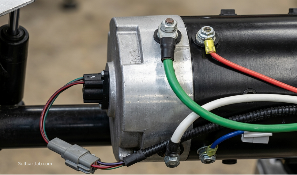
- The Precedent speed sensor is a three-wire Hall-effect device that pulses as a magnet on the armature spins; the controller counts pulses.
- Limp mode is logged when output is above 75% armature PWM with no pulses, but low voltage, a speed setting, or welded-contact logic can also slow the cart.
- On the 2020 system, look for about 15V to 16V supply, a 4.60V to 4.90V signal bias, and a 0V to 4.85V toggle as a wheel turns.
- Run the key-off push test and inspect the magnet before buying a sensor; part 102704901 is a cross-reference to confirm by serial.
The Club Car Precedent speed sensor is a three-wire Hall-effect device on the motor end cap. A rotating magnet on the armature switches the signal wire between low and about 5V, and the controller counts those pulses to work out motor speed and apply walk-away braking. Understanding that it makes a digital pulse, not a smooth analog voltage, is the key to testing it correctly instead of guessing.
Fast diagnostic path: verify the batteries under load, run the key-off push test, inspect the three-pin connector, check the 15V to 16V supply and 4.60V to 4.90V signal bias, then watch the signal toggle while a rear wheel turns. Inspect the magnet before ordering a sensor.
How the Speed-Sensor Circuit Works
The sensor does not create a variable analog voltage proportional to road speed. It switches a digital pulse as poles in the motor magnet pass the Hall element, and the controller counts those pulses. Club Car’s 2020 Precedent service procedure identifies a three-pin connector with a red supply wire, a light-green signal wire, and a purple/white return path on the documented system. Wire colors and controller pins can vary by year and drive system, so confirm the manual by serial.
Club Car records a speed-sensor fault when controller output is above 75% armature PWM and no sensor pulses are detected. The same manual says a high-speed walk-away event is registered if walk-away braking is requested above 2 mph. A missing signal can cause slow operation, lost or abnormal regenerative braking, and a SPEED SENSOR fault, but a reduced top speed is not universal proof, because programmed speed settings, low pack voltage, welded-solenoid detection, or other controller logic can also limit speed.
The Roll-Away Push Test
The push test checks the full chain from magnet through sensor to controller. Use a level, clear surface. First confirm the reverse buzzer works by selecting Reverse. Then put the Tow/Run switch in Run, turn the key off, select Neutral, and slowly push the cart about 3 feet. Club Car’s procedure says the reverse buzzer should sound and motor braking should engage while the vehicle rolls.
If the cart rolls without the buzzer and braking, do not order a sensor yet. A failed buzzer can hide a good speed signal, while an open wire or a controller output fault can make a good sensor look dead. A Club Car Diagnostic Tool can display SPEED PULSES: OFF at rest and ON while the cart is pushed. Without the tool, continue with voltage checks. Low battery voltage can also make a healthy control system act weak, so use the load-testing procedures in the Diagnostics Lab first when the slowdown appears only under acceleration or on hills.
Multimeter Signal Verification
| 2020 Precedent service-manual check | Expected value | An incorrect value points to |
|---|---|---|
| Purple/white terminal, connector unplugged, measured from battery No. 1 positive | Full pack voltage, about 48V to 50V | Open return wiring or controller path |
| Red sensor supply to pack negative, Tow/Run in Run | About 15V to 16V; below 14V fails the manual’s supply check | Supply wire, loaded sensor, or controller output |
| Light-green signal terminal, connector unplugged | 4.60V to 4.90V bias | Signal-wire continuity or controller input |
| Light-green signal back-probed, connector installed, wheel turning slowly | Alternates from about 0V to about 4.85V | Sensor, magnet, connector, or signal wiring if supply and bias already pass |
Use the meter’s min/max function or turn the wheel slowly enough to see both states. A fixed high signal is not automatically a shorted sensor, because the magnet may simply be stopped in the high position, so rotate through several motor positions. If supply and signal bias are correct but the installed signal never toggles, inspect the magnet and sensor seating.
Inspecting the Speed Magnet
The magnet is secured to the end of the motor armature and the sensor mounts over it. Remove power according to the service manual, unplug the three-pin connector, and remove the sensor screws. Inspect the magnet for cracks, rust, wear, looseness, and missing pieces. Club Car’s motor procedure calls for replacement when the magnet is damaged.
No service air-gap dimension is published in the referenced Precedent procedures. The correct method is to install the specified parts cleanly and squarely against the motor end cap, not to add washers or create a guessed gap. Dirt beneath one side of the sensor can tilt it enough to make the pulse intermittent.
Replacement, Part Number, and Torque
Genuine Club Car service package 102704901 is cataloged for the ADC or AMD motor speed-sensor application. Treat that as a cross-reference and confirm by serial, year, and motor number, because Precedent, Tempo, IQ, Excel, GE, and newer AC systems do not all use the same sensor.
| Motor procedure | Magnet screw | Sensor screws |
|---|---|---|
| 2005 Precedent IQ, EJ4-4001 motor | 65 in-lb (7.3 Nm) | 25 in-lb (2.8 Nm) |
| 2020 Precedent service procedure | 65 in-lb (7.3 Nm) | 20 in-lb (2.2 Nm) |
The year-specific difference is exactly why a generic online torque should not be carried across every motor. Use the edition tied to the vehicle serial and motor label. Tighten evenly with an inch-pound wrench, route the harness away from the rotating coupling, reconnect the three-pin plug, and repeat the push test before driving.
What the Controller Behavior Tells You
- Push test passes and SPEED PULSES changes: the sensor circuit works at walking speed, so continue with battery, programmed speed, brake drag, and controller checks.
- Supply is low with the sensor unplugged: trace supply wiring and controller output before installing a new sensor.
- Bias is correct but no toggle occurs: inspect the magnet, seating, connector, and the Hall sensor.
- Toggle reaches the controller but the cart stays slow: read active and stored controller faults and do not assume the sensor is the only limiter.
- Walk-away braking is absent: take the vehicle out of service until the cause is repaired, because roll-away control is a safety function.
After repair, road-test in a clear area, confirm normal pedal-up braking, and scan faults again. More model-specific electrical work is collected in the golf cart repair guides.
A valid diagnosis follows the signal. A healthy documented Precedent circuit supplies about 15V to 16V to the three-wire Hall sensor, biases the signal at 4.60V to 4.90V unplugged, and toggles the installed light-green wire between about 0V and 4.85V as the motor turns. The push test adds a functional check of the buzzer and walk-away braking. Only after those measurements should the magnet, sensor, harness, or controller be named as the failed part.
If the sensor tests good and the Precedent is simply slow on hills, the stock drive is the limit. Our Club Car Precedent speed upgrade guide matches Navitas controller and AC kits to the controller label.
Frequently Asked Questions
How do I test a Club Car Precedent speed sensor?
Start with the key-off push test: put Tow/Run in Run, key off, select Neutral, and push the cart a few feet. The reverse buzzer should sound and motor braking should engage. Then, on the documented 2020 system, check about 15V to 16V on the red supply wire, a 4.60V to 4.90V bias on the light-green signal wire unplugged, and a toggle from about 0V to 4.85V on that signal when a rear wheel turns slowly. Inspect the magnet before ordering a sensor.
What causes limp mode on a Club Car Precedent?
Club Car records a speed-sensor fault when controller output is above 75% armature PWM and no sensor pulses are detected, which can slow the cart, disturb regenerative braking, and set a SPEED SENSOR fault. But a reduced top speed is not proof by itself, because a programmed speed setting, low pack voltage, welded-solenoid detection, or other controller logic can also limit speed.
What is the part number for a Club Car Precedent speed sensor?
Club Car service package 102704901 is cataloged for the ADC or AMD motor speed-sensor application. Treat it as a cross-reference and confirm by serial, year, and motor number, because Precedent, Tempo, IQ, Excel, GE, and newer AC systems do not all use the same sensor.
What torque do the speed sensor and magnet screws take?
It is year-specific, which is exactly why a generic online value should not be reused. The 2005 Precedent IQ EJ4-4001 motor procedure lists 65 in-lb (7.3 Nm) for the magnet screw and 25 in-lb (2.8 Nm) for the sensor screws, while the 2020 procedure lists 65 in-lb for the magnet and 20 in-lb (2.2 Nm) for the sensor screws. Use the edition tied to your vehicle serial and motor label.
