YAMAHA G19 WON’T START
When an electric Yamaha G19 won’t start, the fault is usually a weak pack, a blown 3A control fuse, or a worn switch. This guide tests the dead circuit in the fastest order.
- The G19E path starts with the 48V pack, each 8V battery, the 3A control fuse, and switch inputs.
- No-click and click-with-no-move are different diagnostic branches.
- Avoid invented relay ohms or controller fault charts when the public Yamaha sources do not publish them.
An electric Yamaha G19 that won’t start, no movement, often no response at all, is almost always a break in the low-cost end of the circuit: a tired battery pack, the small 3A control fuse in the service panel, a key switch, the forward/reverse switch caught between positions, or the solenoid. The G19 makes this easy because its trouble spots are few and well known. Work them in order and a multimeter finds the dead link fast.
01 : Check the Batteries First
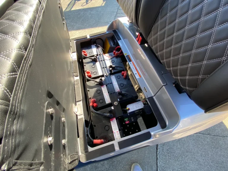
A Yamaha G19 won’t start diagnosis starts with the pack because the G19E is a 48V electric cart. Yamaha’s G19E owner manual says six 8-volt deep-cycle batteries power the cart, and the G19E parts catalog lists battery assembly quantity 6. That confirms the correct stock layout: 6 x 8V, not 8 x 6V. Use 8V individual-battery readings and 48V pack readings when testing.
| 48V flooded G19E pack state | Rested pack voltage | Each 8V battery | Branch |
|---|---|---|---|
| Full, 100% state of charge | 50.93V | 8.49V | Good starting point. Still test under key and pedal load. |
| Half, 50% state of charge | 48.41V | 8.07V | Charge before deep diagnosis if the cart is dead or intermittent. |
| Discharged, 0% state of charge | 45.40V | 7.57V | Do not chase switches first. Recharge and test individual batteries. |
| Under-load clue | Measure pack at batteries and at controller while key/pedal call for drive | One 8V battery much lower than the rest under load is suspect | Battery or cable problem if voltage collapses before the controller can enable. |
Use rested voltage only after the pack has sat idle. U.S. Battery recommends 4 to 6 hours of rest for flooded batteries before trusting open-circuit readings. A fresh-off-charger pack can look artificially high, and a tired pack can look acceptable at rest but sag as soon as the solenoid or controller asks for current.
02 : Why a Yamaha G19 Won’t Start: The 3A Fuse
Older higher-rating wording on many G19 guides is not supported by the Yamaha G19E parts catalog or the G19E owner-manual wiring page reviewed here. The catalog lists fuse JR1-H2151-00-00 with the remark “(3A-BL)”, and the owner-manual wiring diagram labels the control fuse as “FUSE (3 AMP).” The body diagnosis should therefore use a 3A control-circuit fuse for the G19E unless an installed harness or serial-specific service update proves otherwise.
The fuse is in the low-current control side, not the heavy motor cable path. If it is open, the cart can have a charged 48V pack and still show no solenoid click because the key, drive select, relay, buzzer, and control circuit cannot complete their path. Replace only with the specified rating. If a new 3A fuse opens again, do not upsize it. Find the short or rubbed wire.
03 : Key Switch and Forward/Reverse Switch
After pack and fuse, test the switches in the order the signal travels. The G19E parts catalog names the tow/storage switch, F/R control switch, 3A fuse, relay assembly, main switch, buzzer, controller, and six batteries in the electrical section, so the no-start path is not mysterious. It is a sequence.
| G19E no-start test | Expected reading | If this fails | Verified scope |
|---|---|---|---|
| 48V pack | Near 50.93V full rested, near 48.41V at 50% | Charge, then load-test each 8V battery and cable. | Pack benchmark from battery manufacturer data, G19E layout from Yamaha. |
| Main 3A control fuse | Continuity across fuse, 3A blade rating in Yamaha catalog and wiring diagram | Replace with same rating and trace shorts if it opens again. | G19E exact catalog/wiring value. |
| Main/key switch | Continuity in ON and open in OFF, or pack/control voltage out when ON | Repair terminals or replace switch. | Switch part is listed in G19E electrical section. |
| F/R control switch | Continuity or control output only in selected direction | Repair the switch, connector, or selector before solenoid testing. | G19E catalog lists JR1-H2917-01-00 F/R control switch. |
| Tow/storage switch | RUN should allow controller/control circuit wake-up; TOW disables drive for towing/storage | Put in RUN for driving. If output does not change, test switch and wiring. | G19E catalog lists JR1-H2727-00-00 tow/storage switch. |
| Relay/solenoid assembly | Click when key, direction, and pedal inputs call for drive; 48V control feed present across coil path | No click means upstream control fault or failed coil. Click with no drive moves to main contacts and controller B+. | Yamaha catalog lists JR1-H1950-00-00 relay assembly. Public coil-ohm spec not found. |
| Controller B+ supply | Pack voltage present at controller main supply when relay path is closed | If absent, trace relay contacts and cables. If present with good inputs, controller or motor testing is last. | G19E catalog lists JR1-H6510-10-00 control unit. |
04 : Solenoid Test
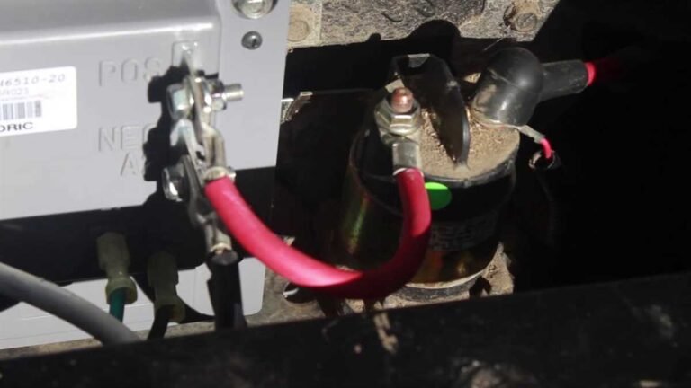
The G19E parts catalog calls the high-current switching component a relay assembly, and many owners call the same job a solenoid. Use the function, not the nickname: small control wiring energizes a coil, then large contacts connect pack power to the controller path. No click means the coil path never completed or the coil failed. A click with no movement means the control path probably worked, but the main contacts, cables, controller supply, or motor path still need testing.
A G19E-exact solenoid or relay coil resistance value was not found in the public owner manual and parts catalog reviewed here. The safe field method is to measure voltage across the coil command wires when the cart is in RUN, key ON, direction selected, and pedal pressed. If the correct control voltage reaches the coil and the relay does not click, replace the relay assembly after confirming the part by serial. If no voltage reaches the coil, walk backward through the 3A fuse, main switch, F/R switch, tow/storage switch, and small wiring.
05 : Controller and Wiring (Last)
The controller is last because it needs every earlier input before it can do anything. The G19E catalog lists control unit JR1-H6510-10-00 in the controller section, along with the tow/storage switch, F/R control switch, 3A fuse, relay assembly, main switch, and battery set. That list is the diagnostic order. Do not replace the controller until pack voltage reaches it and the low-current enable path has been proven.
Check controller B+ and B- while the symptom is present. If pack voltage is present at the batteries but missing at the controller, the fault is still a cable, relay contact, F/R path, or connection. If pack voltage reaches the controller but no output appears with valid inputs, then use the Yamaha service manual or a qualified controller test. Public owner and parts sources do not publish a full controller pin-voltage chart for every G19E failure state.
No-click vs. click: the fork that saves the most time
The fastest split is still the sound from the relay or solenoid. No click means the cheap control circuit is open: discharged pack, open 3A fuse, failed key switch, F/R control switch, tow/storage switch, pedal input, or small wiring. A click means that much of the control path worked, so move to the high-current side: relay contacts, cable voltage drop, controller B+ and B-, motor cables, and controller output. Listen first, then put the meter on the branch the sound points to.
A Yamaha G19E that will not start should be tested as a 48V, 6 x 8V electric cart. A full flooded pack is about 50.93V rested, and the Yamaha sources reviewed identify a 3A control fuse as the visible repair reference. Test pack voltage, the 3A fuse, key switch, F/R control switch, tow/storage switch, relay click, and controller B+ supply in order. If Yamaha does not publish a public coil-ohm or controller-pin value for the exact cart, use the service-manual method and meter the installed circuit rather than guessing.
FAQ
Why won’t my Yamaha G19 start?
An electric Yamaha G19 that won’t start usually has a weak or dead battery pack, a blown 3A control fuse in the service panel behind the batteries, a forward/reverse switch caught between positions, a failed key switch, or a bad relay or solenoid. Test the pack and fuse first, because they are the common low-cost checks.
Where is the fuse on a Yamaha G19?
On the electric G19, look in the black service box right behind the battery pack. The Yamaha sources reviewed for this update identify the control fuse as 3A. If the battery and relay path test good but the cart is dead, remove the cover, locate the fuse, and replace it only with the same rating if it is blown.
Is the Yamaha G19E main control fuse 3A or 10A?
For the G19E material covered here, use a 3A control fuse. Yamaha’s G19E parts catalog identifies the fuse as 3A and the owner-manual wiring diagram labels it as a 3 amp fuse. It protects the low-current control path, not the main motor cable. If the installed harness differs, verify the serial and wiring before installing any fuse, and never upsize an opening fuse.
What does no click versus a click mean on a G19E?
No click points to the low-current enable path: pack state, 3A fuse, key switch, tow/storage switch, F/R control switch, pedal input, or small wiring. A click shows the relay coil has been commanded, but not that its high-current contacts passed power. Then measure pack voltage at the controller side of the relay and check the large cables and controller supply.
Updated July 2026: corrected the G19E fuse rating to 3A and added 6 x 8V pack, switch, relay, and controller test tables.