EZGO MEDALIST NO POWER
When an EZGO Medalist has no power, the break is somewhere from the battery pack to the controller. This guide tests the older Series drive circuit in the fastest order.
- Separate a totally dead cart from a no-drive cart before replacing parts.
- A healthy 36V flooded pack should be checked at rest, by battery, and again under pedal load.
- Medalist wiring varies by resistor-coil and series-drive systems, so confirm the installed circuit before using a test value.
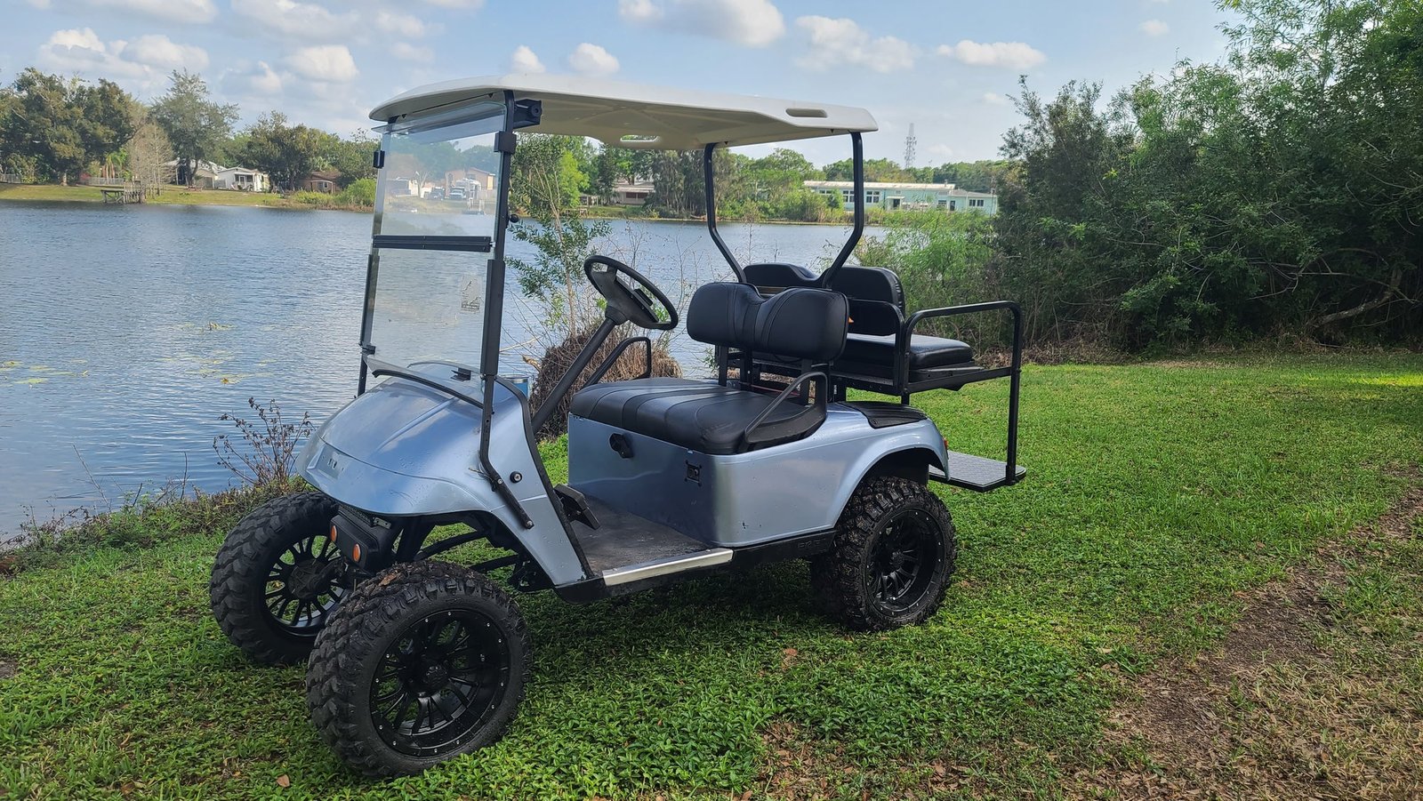
The EZGO Medalist (the early-to-mid 1990s Series cart that preceded the TXT) uses a straightforward resistor-or-Series drive system, which makes a no-power fault very diagnosable. When a Medalist is dead, no movement, maybe no accessories, the fault sits somewhere along battery → key switch → micro-switches → solenoid → controller. Work it from the battery outward and a multimeter finds the dead link quickly, without replacing parts on a guess.
01 : Dead vs. No Drive: Define the Symptom
EZGO Medalist no power needs one correction before testing starts. Medalist is mainly a 1994 to 1995 body generation, and later TXT/DCS service information can overlap mechanically, but it should not be treated as one universal 1994 to 1998 PDS cart. Identify the data plate, controller type, and speed-control layout first. A resistor-coil/V-Glide style cart, a series controller cart, and a DCS cart can all be 36V, but the switch path and controller diagnostics are not the same.
Then define the failure. Completely dead, with no lights or accessories, starts at the battery pack, main cables, key switch, and fuse or charge interlock path if equipped. Accessories present but no movement starts at the pedal switch, F/R micro-switches, solenoid coil, solenoid contacts, and controller B+ and B- supply. The meter should follow the chain rather than jumping straight to the controller.
| 36V flooded pack state | Rested pack voltage | Individual 6V battery | What it means |
|---|---|---|---|
| Full, 100% state of charge | 38.20V | 6.37V | Normal open-circuit target after proper rest. Still load-test if it dies on pedal. |
| Half, 50% state of charge | 36.31V | 6.05V | Enough to click a solenoid on some carts, but not a healthy starting point for diagnosis. |
| Discharged, 0% state of charge | 34.05V | 5.68V | Recharge before diagnosing switches. Deep discharge can mimic a dead circuit. |
| Under-load comparison | Use a proper load or hill symptom test | One battery more than 0.5V below the highest under load is suspect | U.S. Battery gives this as a failure clue during load testing, not a simple rested-voltage test. |
02 : EZGO Medalist No Power: The Drive Circuit
The Medalist drive circuit is still a chain: battery pack, main positive feed, key switch, pedal and direction micro-switches, solenoid coil, solenoid main contacts, controller or resistor speed control, and motor. The E-Z-GO service procedure for electric carts describes testing switches for continuity and testing the solenoid for welded contacts. It also says that if the contacts are not welded and the wiring to the solenoid coil is good, a failed coil means the solenoid is replaced. That is more useful than guessing a coil-ohm value that was not found in the public Medalist sources reviewed here.
- Battery pack: a fully charged 36V flooded pack should rest near 38.20V. Charge, rest, then test under load.
- Key switch: OFF should be open and ON should have continuity, or pack voltage should pass through to the control circuit.
- Micro-switches: a normally open switch should close when actuated. Pedal and direction switches must both match the selected direction.
- Solenoid: no click means the coil is not being energized or the coil has failed. A click with no movement moves the test to the large terminals and controller supply.
For exact wiring colors and controller pin names, use the manual for the exact Medalist or TXT/DCS configuration. Public sources reviewed here support the method, 36V pack benchmark, and continuity logic, but not one universal Medalist solenoid-coil resistance value.
03 : Step-by-Step Test
Lift the rear wheels safely, use insulated tools, and keep the pack connected only for live-voltage steps. If the pack is below a usable charge, stop and charge before diagnosing the controller.
| Test point | Expected reading | If it fails | Scope note |
|---|---|---|---|
| Pack at main positive and main negative | About 38.20V fully charged and rested, 36.31V around 50% | Charge and load-test. If one 6V battery falls more than 0.5V below the highest under load, suspect that battery. | 36V flooded lead-acid benchmark from battery manufacturer data. |
| Key switch | Continuity in ON, open in OFF, or pack voltage in and out when ON | Repair terminals or replace switch before testing downstream parts. | Platform method, exact wire color depends on cart. |
| Pedal micro-switch | Normally open switch closes when pedal mechanism actuates it | Adjust pedal box, repair wiring, or replace switch. | E-Z-GO service manual continuity method. |
| F/R micro-switch or direction switch | Continuity only in selected direction, not between positions | Repair switch, cam, or wiring. A direction switch stuck between positions can disable drive. | Medalist/TXT configuration varies. |
| Solenoid coil feed | 36V control power across the coil command path when key, direction, and pedal are calling for drive | If coil wiring is good but no action, replace solenoid. Public Medalist coil-ohm spec not found. | 36V coil voltage only if the installed solenoid is original-spec 36V. |
| Solenoid large posts | No continuity across large posts when off. With solenoid closed, both large posts should carry pack voltage to pack negative. | Continuity when off means welded contacts. Click with no voltage transfer means bad contacts or cable fault. | E-Z-GO continuity test supports welded-contact diagnosis. |
| Controller B+ and B- | Pack voltage present at controller supply after the solenoid closes | If absent, trace solenoid, cables, and F/R path. If present with good inputs and no output, controller or speed-control assembly is last suspect. | Controller type depends on model year and conversion history. |
04 : Solenoid and Micro-Switches
The solenoid is both a sound test and a meter test. No click means the control circuit has not completed through the key, direction switch, pedal switch, safety interlock, wiring, and coil. A click means the coil side probably worked, but it does not prove the high-current contacts are good. The E-Z-GO service manual’s solenoid continuity check is simple: if the two large terminals show continuity while the solenoid is not energized, the contacts are welded closed and the solenoid is bad.
For a no-click Medalist, start with switch continuity. A normally open switch should show open until actuated and continuity when actuated. If the meter never changes, adjust the cam or replace the switch. If the switches pass but the coil still does not click, check for 36V at the coil when the cart is commanded to drive. If the wiring to the coil is good and the solenoid still does not operate, the coil has failed. A public Medalist-exact solenoid coil resistance value was not found in the sources reviewed, so the article uses voltage, continuity, and functional tests instead of a guessed ohm number.
If the solenoid clicks but the cart will not move, measure on the controller side of the solenoid relative to pack negative. If pack voltage is present on the battery side but not transferred to the controller side under command, suspect the solenoid contacts or cable lugs. If pack voltage is present at controller B+ and B- and all inputs test correctly, only then move to controller diagnosis.
05 : Controller and Wiring
Controller diagnosis depends on what the Medalist actually has. Early resistor-coil style carts use visible resistor coils and a mechanical speed-control switch stack. Later solid-state carts use a controller with a solenoid and smaller input wiring. DCS references apply only to DCS carts, and PDS references do not belong on a stock 1994 to 1995 Medalist unless the cart was converted. The label, harness, and controller case matter more than the body name.
On a resistor-coil cart, inspect the resistor coils, speed-control wiper, switch board, and heat-damaged terminals. A burned resistor or stuck speed switch can look like no controller output because there is no modern controller to blame. On a solid-state series cart, verify pack voltage at B+ and B-, then verify the controller is receiving key, pedal, F/R, and solenoid-state inputs. The E-Z-GO manual example for later 48V controller checks is not a 36V Medalist spec, but it shows the same diagnostic discipline: verify controller supply and required inputs before condemning the controller.
Cables deserve the same attention. A cable can read voltage at rest and collapse under load. After a short failed drive attempt, feel carefully for one warm lug or cable end, then voltage-drop test that cable while current is flowing. Replace hot, corroded, swollen, or stiff cables before buying electronics.
Series vs. resistor-coil Medalists: know which you have
The body name is not enough. A resistor-coil cart has a visible resistor assembly and a switch stack that steps power mechanically. A solid-state series cart has a controller and solenoid-controlled high-current feed. A DCS cart uses a different controller and diagnostic path, while PDS is a later TXT-era system rather than a stock Medalist assumption. Look under the seat and at the controller area before ordering parts. If there is a resistor bank, test the resistor coils and wiper/switch plate. If there is a controller, verify B+ and B- supply and required inputs. If a previous owner converted the cart, document the controller model and wiring before using any year-based diagram.
Age-related faults to expect on a Medalist
Age makes the cheap failures more common than the expensive ones. Battery cables corrode inside the insulation, key-switch terminals oxidize, pedal-box micro-switches go out of adjustment, and solenoid lugs loosen from vibration. A rested voltage reading can look acceptable while a cable or battery collapses under pedal load. Clean and tighten the main cables, inspect the pedal box, confirm switch continuity, and load-test the pack before replacing a controller. On a decades-old 36V cart, a proven bad cable is a much better find than an unproven controller guess.
An EZGO Medalist with no power is a 36V chain-break diagnosis. A full flooded pack should rest near 38.20V, and a 50% pack is around 36.31V. If the pack passes under load, test key switch continuity, pedal and F/R micro-switch continuity, solenoid coil voltage, solenoid contact continuity, and controller B+ and B- in that order. The public sources reviewed did not publish one Medalist-exact solenoid coil resistance or universal controller test value, so the correct answer is to meter the installed system by type rather than inventing a number.
FAQ
Why does my EZGO Medalist have no power?
An EZGO Medalist with no power usually has a dead or weak battery pack, a corroded connection, a failed key switch, a stuck micro-switch, or a bad solenoid. Test from the battery outward, pack voltage and connections first, to find where power stops along the drive circuit.
How do I test an EZGO Medalist solenoid?
With the key on, direction selected, and pedal pressed, listen for a click and meter the small coil terminals. An original 36V setup should receive approximately pack voltage when the control circuit is valid. No click with that command points to the coil or its connection. A click does not prove the large contacts pass current, so compare voltage on the battery and controller sides while commanded. The public Medalist sources used here do not publish one universal coil-ohm or terminal-drop limit.
Does an EZGO Medalist have a fuse or reset button?
Do not assume a single reset button. Medalists can retain their original resistor-coil hardware or have a later controller conversion, so inspect the actual wiring, control box, and any inline fuse holder before replacing parts. Check pack voltage, cables, key and pedal-switch continuity, then test every installed fuse with a meter. Replace an opened fuse only with its marked rating and find the short if it opens again.
Is a Medalist a series cart or a resistor-coil cart?
The body name alone does not decide it. A resistor-coil cart has a visible resistor bank and mechanical speed-switch stack. A solid-state series setup has a controller and a solenoid-controlled high-current path. A converted cart may differ again. Identify the hardware under the seat before using a wiring diagram or ordering a solenoid, controller, or resistor part.